In Which Diagram Does the Voltmeter Read Almost Zero?

Meters
Analogue | Digital | Voltmeters | Ammeters | Galvanometers | Ohmmeters
Next Page: Multimeters
As well Run across: Voltage and Current
Analogue brandish
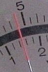
Analogue displays have a arrow which moves over a graduated scale. They can be difficult to read because of the need to piece of work out the value of the smallest scale sectionalisation. For case the scale in the film has 10 small-scale divisions between 0 and ane so each small partitioning represents 0.one. The reading is therefore i.25V (the pointer is estimated to be halfway betwixt one.2 and i.3).
The maximum reading of an analogue meter is called full-scale deflection or FSD (it is 5V in the example shown).
Analogue meters must be continued the correct way round to forbid them being damaged when the pointer tries to move in the incorrect direction. They are useful for monitoring continously changing values (such as the voltage across a capacitor discharging) and they tin can be expert for quick rough readings because the movement of the pointer tin can be seen without looking away from the excursion under examination.
Taking accurate readings
To take an accurate reading from an analogue scale you must have your middle in line with the pointer. Avert looking at an angle from the left or right because y'all will see a reading which is a little also high or besides low. Many analogue meters have a small strip of mirror along the scale to help you lot. When your eye is in the correct position the reflection of the pointer is hidden behind the pointer itself. If you tin can run across the reflection you are looking at an angle.
Instead of a mirror, some meters accept a twisted pointer to assistance accurate readings. The end of the pointer is turned through ninety° then it appears very thin when viewed correctly. The meter shown in the galvanometers section has a twisted arrow although it is besides small to see in the picture.
 Correct | 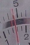 Wrong |
Digital brandish
Values can be read directly from digital displays so they are easy to read accurately. Information technology is normal for the least meaning digit (on the right) to continually alter betwixt two or three values, this is a characteristic of the way digital meters work, not an error. Normally you will not need dandy precision and this digit can exist ignored or rounded up.
Digital meters may exist connected either way round without damage, they will show a minus sign (-) when connected in reverse. If you exceed the maximum reading almost digital meters prove an near bare display with simply a one on the left-hand side.
All digital meters comprise a bombardment to ability the display so they use about no ability from the excursion under exam. This means that digital voltmeters have a very high resistance (usually called input impedance) of at least 1M![]() (often 10M
(often 10M![]() ) and they are very unlikely to impact the circuit under test.
) and they are very unlikely to impact the circuit under test.

For general use digital meters are the all-time type
They are piece of cake to read, they may be connected in reverse and they are unlikely to affect the circuit under test.
Connecting meters
It is important to connect meters the correct way circular:
- The positive final of the meter, marked + or coloured red should be connected nearest to + on the battery or power supply.
- The negative terminal of the meter, marked - or coloured black should be connected nearest to - on the battery or ability supply.
Voltmeters

- Voltmeters measure out voltage.
- Voltage is measured in volts, 5.
- Voltmeters are continued in parallel across components.
- Voltmeters have a very high resistance.
Connecting a voltmeter in parallel
Measuring voltage at a point
When testing circuits you often demand to notice the voltages at various points, for example the voltage at pin ii of a 555 timer IC. This can seem confusing - where should you connect the second voltmeter lead?

- Connect the black (negative -) voltmeter pb to 0V, normally the negative last of the battery or ability supply.
- Connect the reddish (positive +) voltmeter lead to the bespeak you where you need to measure out the voltage.
- The black lead can be left permanently connected to 0V while you lot use the blood-red lead as a probe to measure voltages at diverse points.
- You may wish to apply a crocodile clip on the black lead to hold it in place.
Voltage at a point actually means the voltage difference betwixt that point and 0V (nothing volts) which is normally the negative terminal of the battery or power supply. Usually 0V will be labelled on the circuit diagram equally a reminder.
Counterpart meters take a little power from the circuit under test to operate their pointer. This may upset the circuit and requite an incorrect reading. To avoid this voltmeters should accept a resistance of at least 10 times the circuit resistance (take this to exist the highest resistor value near where the meter is connected).
Nearly analogue voltmeters used in schoolhouse science are not suitable for electronics because their resistance is also low, typically a few thou![]() . 100k
. 100k![]() or more is required for most electronics circuits.
or more is required for most electronics circuits.
Ammeters

- Ammeters measure electric current.
- Current is measured in amps (amperes), A.
1A is quite big, so mA (milliamps) and µA (microamps) are often used. 1000mA = 1A, 1000µA = 1mA, 1000000µA = 1A. - Ammeters are continued in series.
To connect in series yous must break the circuit and put the ammeter beyond the gap, as shown in the diagram. - Ammeters accept a very low resistance.
The demand to break the circuit to connect in serial means that ammeters are difficult to use on soldered circuits. About testing in electronics is done with voltmeters which can be easily continued without disturbing circuits.
Connecting an ammeter in series
Galvanometers

Galvanometers are very sensitive meters which are used to mensurate tiny currents, commonly 1mA or less. They are used to make all types of analogue meters by calculation suitable resistors as shown in the diagrams below.

Making a Voltmeter
A galvanometer with a high resistance
multiplier in series to brand a voltmeter.
Making an Ammeter
A galvanometer with a low resistance
shunt in parallel to make an ammeter.

The photograph shows an educational 100µA galvanometer with multiplier and shunt. This meter is unusual in allowing small reverse readings to be shown: the maximum meter current is 100µA (or 20µA reverse).
Ohmmeters

An ohmmeter is used to measure resistance in ohms (![]() ).
).
Ohmmeters are rarely found as separate meters just all standard multimeters have an ohmmeter setting.
ane![]() is quite small and so k
is quite small and so k![]() and M
and M![]() are often used.
are often used.
1k![]() = k
= k![]()
1M![]() = 1000k
= 1000k![]() = million
= million![]()
Multimeters
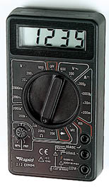
Multimeters are very useful test instruments. By operating a multi-position switch on the meter they tin be rapidly and easily set to exist a voltmeter, an ammeter or an ohmmeter. They accept several settings (chosen 'ranges') for each blazon of meter and the choice of Air conditioning or DC.
Some multimeters have boosted features such equally transistor testing and ranges for measuring capacitance and frequency.
A digital multimeter is the best choice for your start multimeter, fifty-fifty the cheapest will exist suitable for testing simple projects and I recommend this one from Rapid Electronics: Digital Multimeter (basic)
For further information please see the Multimeters page.
Multimeter photograph © Rapid Electronics.
Adjacent Folio: Multimeters | Study
Source: https://electronicsclub.info/meters.htm
0 Response to "In Which Diagram Does the Voltmeter Read Almost Zero?"
Postar um comentário